Datum Machine
Industrial cutting accuracy is rarely lost through one dramatic mistake. It usually slips through small details: a dull blade, unstable material, or an unchecked measurement. In a busy workshop, a difference of 0.5 millimeters can affect fit, waste, and delivery schedules. This guide examines how to improve accuracy in industrial cutting operations through practical controls and repeatable habits. It focuses on machine setup, tooling, material support, calibration, and operator judgment. Real production experience matters here. A cutting plan may look correct on paper, yet behave differently when heat, vibration, or changing stock thickness enters the process.
The ten tips ahead are designed for teams using saws, lasers, waterjets, plasma systems, or similar equipment. Each recommendation connects measurement with action. Operators should verify reference points, inspect consumables, and record results before adjusting settings. Simple records often reveal patterns that memory misses. Good accuracy also depends on preventive maintenance and clear quality checks, not only advanced software. Small details matter. Still, no method is perfect. A setting that succeeds on stainless steel may fail on aluminum, and a trusted fixture can slowly lose repeatability. That uncertainty deserves attention, not excuses. The goal is not to promise zero error. It is to build a controlled process that detects drift early, reduces scrap, and supports safer, more reliable production. The following guidance combines established manufacturing practice with practical observations from the cutting floor, while leaving room for testing and honest review.
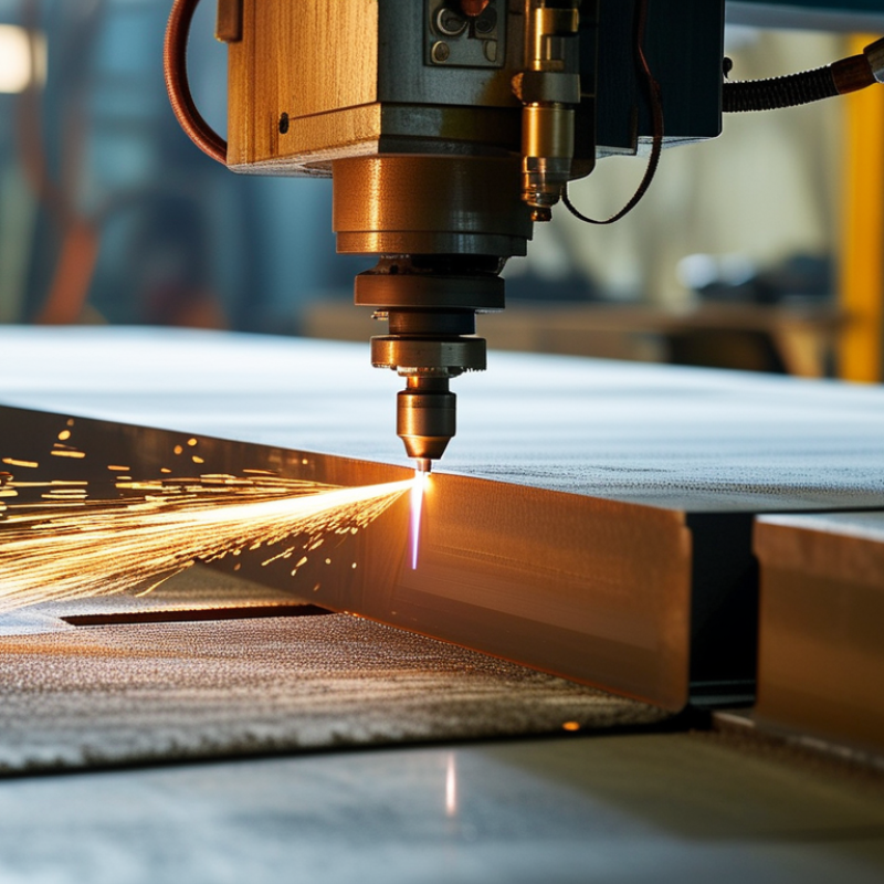
Cutting accuracy describes how closely a finished part matches its specified dimensions, angles, and edge positions. It is usually assessed against a drawing tolerance, such as ±0.1 mm. Accuracy includes both precision and repeatability. A machine may produce consistent parts that are consistently wrong. That is not acceptable accuracy.
Real production conditions make this harder. Material thickness, hardness, internal stress, and surface condition can change the cutting result. Heat may expand the workpiece or alter the cut path. Tool wear can widen the kerf and create a tapered edge. Machine rigidity matters too. Vibration, loose fixtures, and poor alignment often leave visible marks on the edge.
Measurement is another key factor. Operators should inspect critical dimensions with calibrated tools and record results during production. Environmental temperature can affect both the material and measuring equipment. Software settings, cutting speed, feed rate, and power must match the material. Small changes matter.
I have seen accurate settings fail after a material batch changed. A clean table did not fix the problem. The real cause was internal stress. This is easy to miss. Regular calibration helps, but it cannot replace practical observation. Operators should compare the first cut with the drawing, inspect the edge closely, and adjust one variable at a time. Even then, some uncertainty remains.
Accuracy in industrial cutting starts with matching the machine to the material, thickness, and required tolerance. A rigid frame reduces vibration during long cuts. Check the table for flatness before production begins. Small movement can create visible taper. Measure twice.
Choose a tool designed for the material, not simply the fastest option. Tooth geometry, edge condition, and tool diameter affect heat and chip removal. A dull edge may leave burrs, even when the machine appears correctly aligned. Inspect tools under good lighting before each shift. Replace damaged tools early. This costs less than correcting an entire batch.
Cutting parameters need controlled adjustment. Set speed, feed rate, depth of cut, and coolant flow according to material behavior. Begin with verified values from technical data, then make small changes after test cuts. Listen for abnormal vibration and inspect the cut surface. A clean edge does not always prove perfect accuracy. Check dimensions with calibrated instruments at several points. Record temperature, tool life, and measured results for repeatable work. In practice, operators sometimes increase speed too quickly to meet a schedule. That choice can shorten tool life and reduce consistency. Review the process when results drift, because the original setting may no longer suit the machine, tool, or material.
Accuracy in Industrial Cutting: 10 Tips to Improve Accuracy
Alignment begins before the blade, torch, or tool touches material. Confirm the material is flat, clean, and supported across its full length. Even a small burr can tilt a workpiece and transfer error into every cut. Mark the reference edge, then align that edge with the machine datum. Do not trust visual alignment alone. A calibrated rule, probe, or laser can reveal a 1 mm gap quickly. Secure fixtures firmly, but avoid excessive clamping force that can deform thin sheets.
ISO 230-1 emphasizes evaluating machine-tool accuracy under defined environmental and measurement conditions. Temperature matters. A 5°C change can alter long steel components enough to affect close tolerances. The 2023 World Economic Forum Global Lighthouse Network report recorded average productivity gains of about 31% at leading digitally enabled factories. Measurement discipline supports those gains, even without complex automation. Record fixture position, material thickness, and the first-cut result. That record makes recurring drift easier to trace.
I have seen teams adjust cutting speed before checking fixture movement. That assumption fails. A square fixture may shift after repeated loading, especially when chips collect beneath it. Check contact points after every setup change. Use a test cut on costly materials. It is cheaper than discovering ten inaccurate parts. Leave a small allowance when the material’s flatness is uncertain, then inspect the edge and final dimension. Perfect alignment is rarely permanent. Recheck it.
Align materials, workpieces, and fixtures before cutting to reduce dimensional deviation and improve repeatability.
The chart compares average dimensional deviation measured during four common cutting setup conditions. Squaring the workpiece, checking material flatness, securing the fixture, and verifying the cutting path can substantially reduce error before the machine starts.
Tip 1: Select cutting speed and feed rates from measured material behavior, not habit.
Tip 2: Keep coolant flow steady across the cutting zone. A dry corner can distort dimensions quickly.
Tip 3: Check heat marks after each trial batch. They often reveal excessive friction before accuracy falls.
Tip 4: Allow thick workpieces to reach a stable temperature before final measurement. I have seen accurate cuts become wrong after cooling.
Tip 5: Secure the workpiece with even clamping pressure, without crushing thin sections.
Tip 6: Shorten tool extension whenever possible. Long tools amplify small machine movements.
Tip 7: Inspect the table, guides, and fasteners for looseness.
Tip 8: Use a stable cutting path and avoid sudden direction changes. Small changes matter.
Machine stability is not always obvious, especially during long production runs.
Tip 9: Record edge condition, cut length, and dimensional results after repeated cycles. Replace worn tooling before burrs become severe.
Tip 10: Verify alignment with calibrated gauges at scheduled intervals. Do not trust a single reading.
I would also review failed parts without blame; the cause may involve heat, vibration, clamping, or measurement technique. These variables can overlap, and a familiar setting may still be wrong for a new material batch.
Industrial cutting accuracy depends on what happens before and after each cut. Clean the cutting bed daily, especially around clamps and guide rails. A thin layer of dust can shift material by several millimeters. Inspect the blade for chips, uneven wear, or heat discoloration. Small damage often creates rough edges and inconsistent dimensions. Check alignment with a calibrated square before production begins. Do not trust yesterday’s settings.
Maintenance should follow a written schedule, not memory. Verify blade tension, fastener tightness, lubrication points, and sensor positions. Recalibrate measuring systems after heavy use or accidental impact. Then perform a sample cut using the actual material thickness. Measure length, width, angle, and edge quality with suitable instruments. Record the results beside the machine, including temperature and operator observations. Paper records still matter. Digital logs can miss practical details.
Regular inspection reveals patterns that single checks cannot show. If one corner repeatedly measures short, examine alignment before changing software settings. Replace worn guides early, but do not replace parts without confirming the cause. That mistake wastes time and may hide a deeper problem. Our inspection routine is not flawless. Operators sometimes overlook gradual vibration during busy shifts. A short pause can expose it: listen for unusual noise and feel for uneven movement. Review rejected pieces each week and compare them with maintenance records. Accuracy improves when measurements lead to specific adjustments, not assumptions.
| No. | Accuracy Improvement Tip | Inspection or Maintenance Task | Key Measurement | Recommended Frequency | Suggested Acceptance Target | Likely Accuracy Benefit |
|---|---|---|---|---|---|---|
| 1 | Verify machine calibration | Check axis travel against a certified scale, laser interferometer, or calibrated artifact across the normal working range. | Positioning error and repeatability | Monthly and after major repairs | Within the machine builder's specified tolerance; commonly about ±0.05 mm for precision sheet cutting equipment | Prevents cumulative dimensional errors over long cuts. |
| 2 | Inspect and align the cutting head | Check nozzle centering, head perpendicularity, lens condition, and focal alignment using a test coupon. | Nozzle concentricity and focal position | At each shift start and after a collision | Nozzle visibly centered; focal position within the approved process window | Reduces taper, uneven kerf width, and localized edge defects. |
| 3 | Maintain a clean optical path | Inspect protective windows, lenses, mirrors, and optical housings for contamination, cracks, or heat marks. | Surface contamination and optical damage | Every shift; replace according to condition | No visible cracks, burns, or contamination in the active optical area | Maintains stable energy delivery and consistent cut quality. |
| 4 | Control material flatness and position | Measure sheet thickness, flatness, and datum location before cutting; secure the workpiece against movement. | Thickness variation and workpiece displacement | Every material batch or setup change | Material thickness within the programmed range; no visible rocking or unsupported span | Limits dimensional variation caused by deflection and incorrect focus height. |
| 5 | Optimize cutting parameters | Use a controlled test matrix to verify speed, power, assist-gas pressure, pierce time, and focal position for each material and thickness. | Kerf width, dross, heat-affected zone, and edge squareness | For every new material, thickness, or process change | Stable kerf and edge quality across the full test coupon | Improves dimensional consistency and reduces heat-related distortion. |
| 6 | Check assist-gas delivery | Inspect filters, regulators, hoses, valves, and connections; compare actual pressure with the programmed value. | Pressure stability and flow restriction | Daily pressure check; filter inspection monthly | Actual pressure remains within ±5% of the approved process setting | Reduces dross, incomplete cuts, and variation along the cut path. |
| 7 | Inspect the motion system | Clean and lubricate guideways, inspect racks or ball screws, and check for backlash, vibration, or abnormal noise. | Backlash, vibration, and axis repeatability | Weekly inspection; lubrication per service schedule | No measurable backlash beyond the machine specification | Improves corner accuracy and repeatability during rapid direction changes. |
| 8 | Inspect cut edges and kerf geometry | Use calipers, a microscope, or a coordinate measuring system to inspect sample parts from different areas of the sheet. | Part size, kerf width, taper, burr, and squareness | First-piece inspection and periodic sampling | Dimensions meet the drawing tolerance; edge defects remain within the approved quality limit | Detects drift before a complete batch is produced. |
| 9 | Keep the cutting table stable | Remove slag and scrap, inspect support slats, and verify that the table is level and free from loose supports. | Table flatness and support condition | Daily cleaning; level check monthly | Workpiece remains adequately supported without contact with accumulated slag | Reduces distortion, collision risk, and inconsistent cutting height. |
| 10 | Record results and schedule corrective maintenance | Trend inspection data, identify recurring defects, and link each deviation to a maintenance or parameter adjustment action. | First-pass yield, rework rate, and dimensional deviation | Review every shift; formal trend review weekly | Stable first-pass yield and no repeated deviation without documented corrective action | Turns inspection findings into measurable, continuous accuracy improvement. |
| Recommended targets should be confirmed against the machine specification, material grade, drawing tolerance, and applicable quality requirements before production use. | ||||||
The material should be flat, clean, and fully supported. A small burr can tilt the workpiece and affect every cut. Mark one reference edge. Align it with the machine datum. Visual checks alone are unreliable.
Use a calibrated rule, probe, or laser. A 1 mm gap can change the final dimension. Check the full contact line, not only one corner. Small gaps matter.
Fixtures must stay firm during cutting. Excessive force can deform thin sheets. Check contact points after setup changes. Chips beneath a fixture can cause movement. We sometimes blame cutting speed too quickly.
Temperature changes can expand or contract long steel components. A 5°C shift may affect close tolerances. Record the temperature with each inspection. This detail is easy to overlook.
Record fixture position, material thickness, and the first-cut result. Measure length, width, angle, and edge quality. Add operator observations beside the machine. Paper records can reveal details digital logs miss.
Clean the cutting bed daily, especially around clamps and guide rails. Dust can shift material by several millimeters. Remove chips beneath fixtures before loading new workpieces. Clean surfaces support repeatable alignment.
Inspect blade condition, blade tension, fasteners, lubrication points, guides, and sensors. Look for chips, uneven wear, and heat discoloration. Check for unusual noise or uneven movement. Listen carefully.
Examine fixture and machine alignment before changing software settings. Check for worn guides, vibration, or debris under the fixture. Confirm the cause before replacing parts. Guessing wastes time and may hide deeper problems.
Leave a small allowance before final sizing. Inspect the edge and final dimension afterward. This approach reduces risk with uneven material. It is not perfect, but it can prevent costly rework.
Compare rejected parts with maintenance records each week. Look for repeated errors, such as one short corner. Use measurements to guide specific adjustments. Our routine is not flawless, so regular review remains necessary.
Improving accuracy in industrial cutting operations begins with understanding the factors that affect dimensional consistency, edge quality, and repeatability. The key is to choose a machine, cutting tool, and operating parameters that match the material, thickness, geometry, and required tolerance. Before cutting, operators should properly align the material, secure the workpiece, and check that fixtures are stable and correctly positioned. These steps help prevent movement, misalignment, and unwanted variation during production.
To understand how to improve accuracy in industrial cutting operations, it is also important to control heat, vibration, tool wear, and machine stability. Appropriate cutting speeds, feeds, cooling methods, and support systems can reduce distortion and improve surface results. Regular inspection of dimensions and cut quality allows problems to be identified early. Scheduled maintenance, calibration, tool replacement, and performance checks further support consistent accuracy, reduce waste, and improve the reliability of the entire cutting process.
